2011年4月16日 星期六
2010年5月7日 星期五
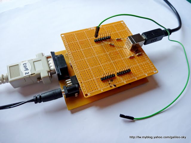
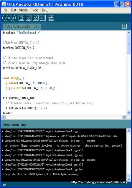
Fixed the problem of compiling UsbKeyboard in arduino_0018
As we know the original design of USBKeyboard library only works in arduino 0016.
I've just fixed the problem of compiling the USBKeyboard library.
My approach is simply to modify the header file usbdrv.h.

In usbdrv.h
Add the following statements for usbInit() and usbPoll().
#ifdef __cplusplus
extern "C"{
#endif
USB_PUBLIC void usbInit(void);
#ifdef __cplusplus
} // extern "C"
#endif
#ifdef __cplusplus
extern "C"{
#endif
USB_PUBLIC void usbPoll(void);
#ifdef __cplusplus
} // extern "C"
#endif
And then copy the UsbKeyboard folder to the libraries folder of the arduino enviroment. You may delete the object files (*.o), arduino IDE will compile source code files (including the assembler code). Load and compile (verify) the UsbKeyboardDemo sketch. It should work.
2010年5月3日 星期一

2008年8月10日 星期日
RF link with Arduino
More photos can be found in the RF link album:
http://picasaweb.google.com/galileosky/RFLink
Here I use two Arduino boards for the RF link experiments.
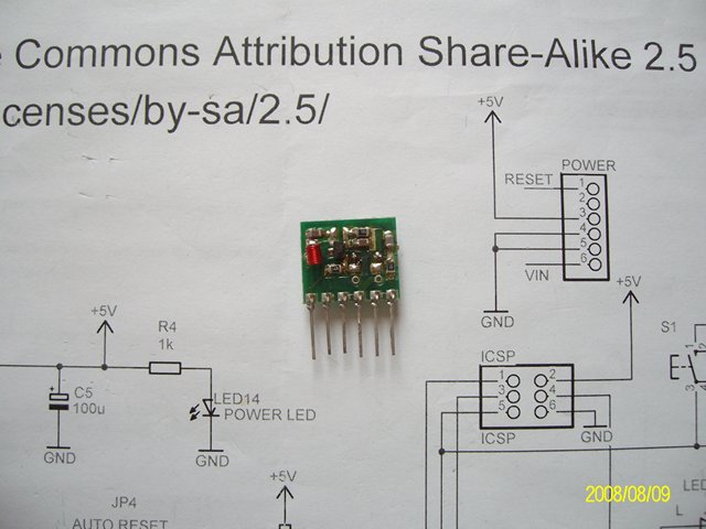
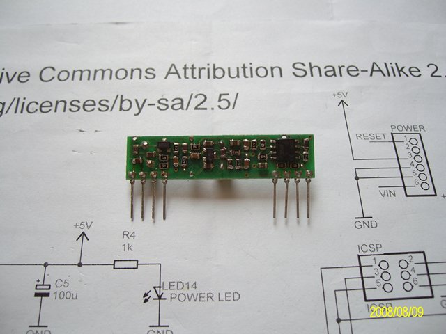
The RF TX and RX modules are off-the-shelf products which you can buy them from the local radio shops. The modules I use are 315 MHz AM.

The TX module.
The RX module.
Arduino shield for the TX module. (I re-use the shield of Nunchuck.)

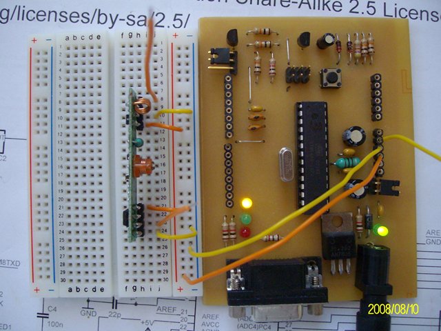
For RX module, I use breadboard for quick setup.
http://picasaweb.google.com/galileosky/RFLink
Here I use two Arduino boards for the RF link experiments.
The RF TX and RX modules are off-the-shelf products which you can buy them from the local radio shops. The modules I use are 315 MHz AM.
The TX module.
The RX module.
Arduino shield for the TX module. (I re-use the shield of Nunchuck.)
For RX module, I use breadboard for quick setup.
2008年8月4日 星期一
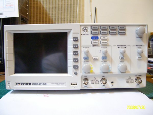
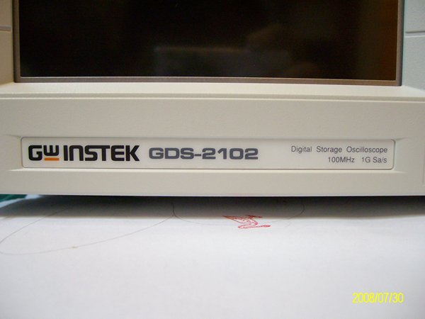
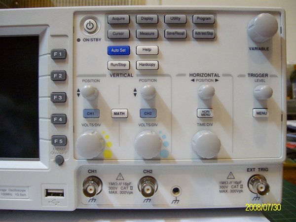
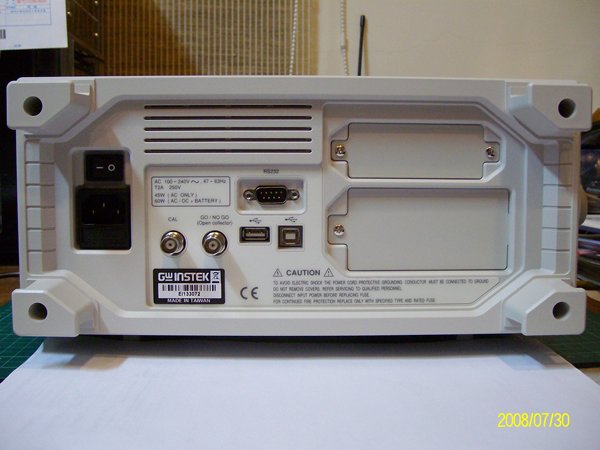
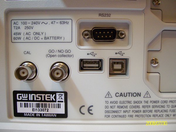
New oscilloscope
This is the new oscilloscope I purchased last week.
My older one (GOS-658G) is out of order when I was trying to measure the level shifter voltage of the Wii Nunchuck interface shield. Besides, 658G is an analog OSC, which is not very useful when measuring transient signals or digital data. So finally, I made up my mind to get a digital OSC.
This one is 100MHz DSO, with 1GS/s sampling rate. The memory depth is 25K points. By the way, it has USB mass storage port, which is very convenient when waveform storaging is demanded.
For a Tek DSO, these features may cost me twice or more.
2008年8月1日 星期五
ATmega168 arrived
I bought these ATmega168-20PU from the internet auction site. Not cheap, but this is the most convenient way to get these parts. I couldn't find them in the local radio shop. Even the on-line shope of the Atmel agent doesn't carry this part.
Basically, these parts will be used for my arduino adventure in the near future.
Basically, these parts will be used for my arduino adventure in the near future.


2008年7月27日 星期日
When Arduino Meets Wii Nunchuck
When Arduino Meets Wii Nunchuck
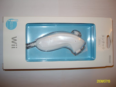
The Nintendo Wii Nunchuck controller.
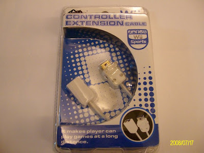
The Wii Nunchuck extension cable.
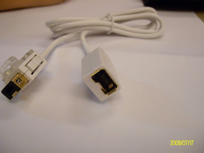
The extension cable out of the box.
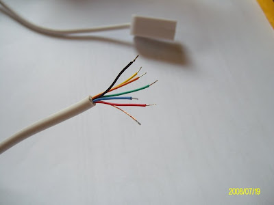
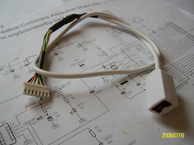
Cut the extension cable and we got 6 color coded wires plus one shield wire.
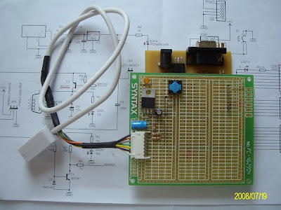
Make it a Molex 2.5 mm connector and secure the conjunctions with heat shrink tube.
Find the best locations for the headers on the multi-purpose PCB board.
Since the distance between the two digital headers is not standard 2.54mm pitch,
I have to sacrifice one of them on this shield.
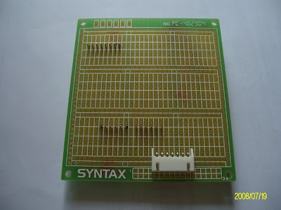
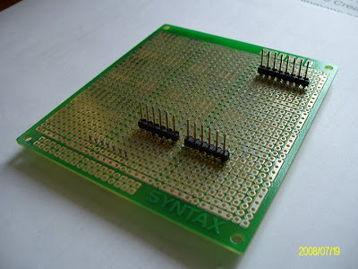
The headers soldered in place
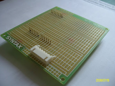
The Molex connector soldered in place.
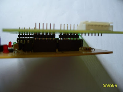
This is how the shield connected with Arduino.
I let the headers protrude out of the PCB on component side on purpose.
This way I can use the jump wires to connect them to the breadboard for other experiments.
Also I can clip the probe on them to monitor the Arduino ouputs or inputs.
The Nunchuck shield mounted on Arduino.
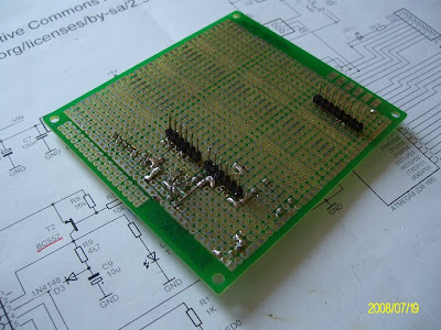
The soldering side of the Nunchuck shield.
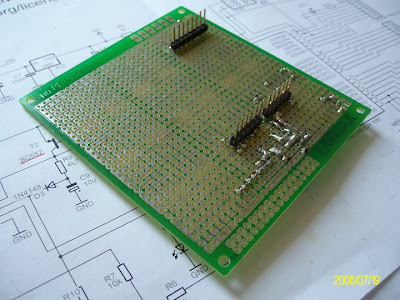
Another view of the soldering side of the Nunchuck shield.
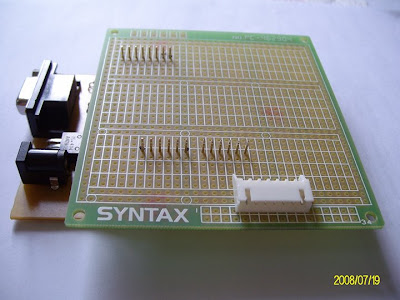
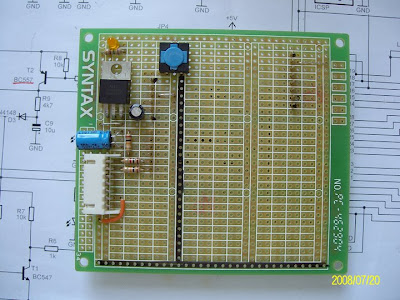
The component side of the Nunchuck shield. Most of the area is not used yet.
The left most area is planned to be the 3.3V and Nunchuck area.
Since the RESET button on Arduino is not easy to access on this configuration, a RESET button installed on the Nunchuck shield.
The Nunchuck shield mounted on Arduino.
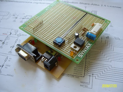
This is the first version of the Nunchuck shield I built.
The 3.3V regulator I used is LD1117. Simple and efficient to get 3.3V from 5~12V input voltage for Nunchuck.
I used two resistors as the level shifting devices between Nunchuck and Arduino.
But later on, I found it don't work. The low level can't reach 0.6V or lower.
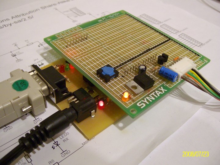
Power on the Arduino and Nunchuck shield.
The amber LED on the Nunchuck shield is power indicator of 3.3V.
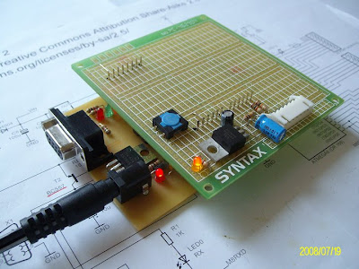
The Nunchuck extension cable connected.
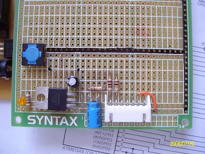
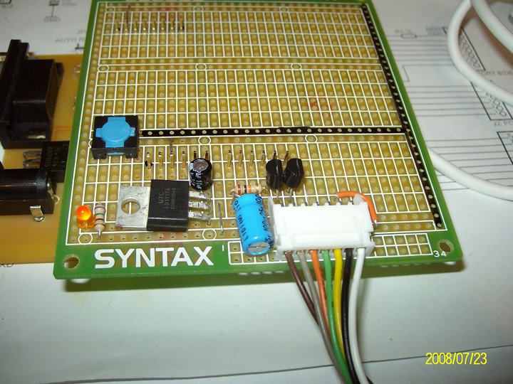
This is the 3rd (final) version of the Nunchuck shield board.
Actually I'd tried to replace the resistors with diode (1N4007) to try to get the logic low level to 0.6V. But it didn't work either. So in the final version, I used two N-channel MOSFET (2N7000) as the level shifters. The logic low level now reaches as low as 0.2~0.3V. It works perfectly now.
In fact, I found the N-channel MOSFET being the good device to drive high current (or power) circuits for MCU designs.
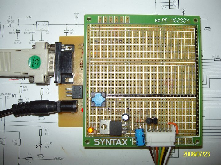
See the two TO-92 devices? They are the level shifters MOSFETs (2N7000).
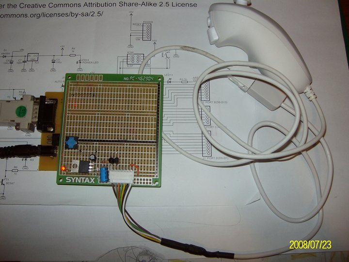
Arduino + Nunchuck shield board transimitting the Nunchuck readout via the serial port.
Arduino + Nunchuck shield board + Nunchuck on line.
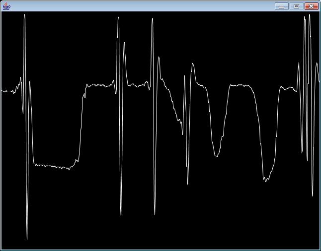
The X-accelerometer readout when I waved the Nunchuck.
The Nintendo Wii Nunchuck controller.
The Wii Nunchuck extension cable.
The extension cable out of the box.
Cut the extension cable and we got 6 color coded wires plus one shield wire.
Make it a Molex 2.5 mm connector and secure the conjunctions with heat shrink tube.
Find the best locations for the headers on the multi-purpose PCB board.
Since the distance between the two digital headers is not standard 2.54mm pitch,
I have to sacrifice one of them on this shield.
The headers soldered in place
The Molex connector soldered in place.
This is how the shield connected with Arduino.
I let the headers protrude out of the PCB on component side on purpose.
This way I can use the jump wires to connect them to the breadboard for other experiments.
Also I can clip the probe on them to monitor the Arduino ouputs or inputs.
The Nunchuck shield mounted on Arduino.
The soldering side of the Nunchuck shield.
Another view of the soldering side of the Nunchuck shield.
The component side of the Nunchuck shield. Most of the area is not used yet.
The left most area is planned to be the 3.3V and Nunchuck area.
Since the RESET button on Arduino is not easy to access on this configuration, a RESET button installed on the Nunchuck shield.
The Nunchuck shield mounted on Arduino.
This is the first version of the Nunchuck shield I built.
The 3.3V regulator I used is LD1117. Simple and efficient to get 3.3V from 5~12V input voltage for Nunchuck.
I used two resistors as the level shifting devices between Nunchuck and Arduino.
But later on, I found it don't work. The low level can't reach 0.6V or lower.
Power on the Arduino and Nunchuck shield.
The amber LED on the Nunchuck shield is power indicator of 3.3V.
The Nunchuck extension cable connected.
This is the 3rd (final) version of the Nunchuck shield board.
Actually I'd tried to replace the resistors with diode (1N4007) to try to get the logic low level to 0.6V. But it didn't work either. So in the final version, I used two N-channel MOSFET (2N7000) as the level shifters. The logic low level now reaches as low as 0.2~0.3V. It works perfectly now.
In fact, I found the N-channel MOSFET being the good device to drive high current (or power) circuits for MCU designs.
See the two TO-92 devices? They are the level shifters MOSFETs (2N7000).
Arduino + Nunchuck shield board transimitting the Nunchuck readout via the serial port.
Arduino + Nunchuck shield board + Nunchuck on line.
The X-accelerometer readout when I waved the Nunchuck.
訂閱:
文章 (Atom)