When Arduino Meets Wii Nunchuck
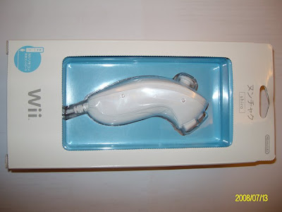
The Nintendo Wii Nunchuck controller.
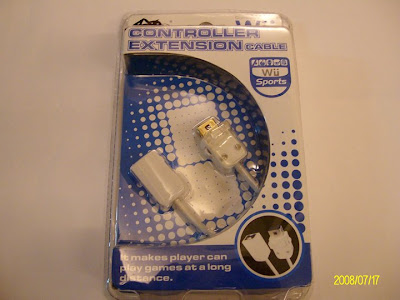
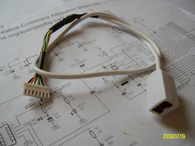
The Wii Nunchuck extension cable.
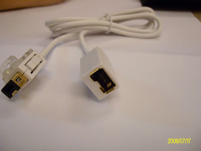
The extension cable out of the box.
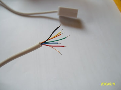
Cut the extension cable and we got 6 color coded wires plus one shield wire.
Make it a Molex 2.5 mm connector and secure the conjunctions with heat shrink tube.
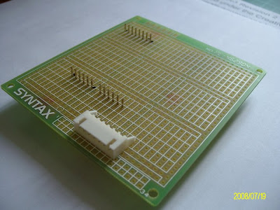
Find the best locations for the headers on the multi-purpose PCB board.
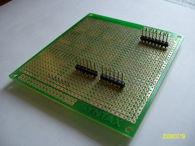
Since the distance between the two digital headers is not standard 2.54mm pitch,
I have to sacrifice one of them on this shield.
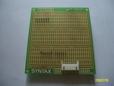
The headers soldered in place
The Molex connector soldered in place.
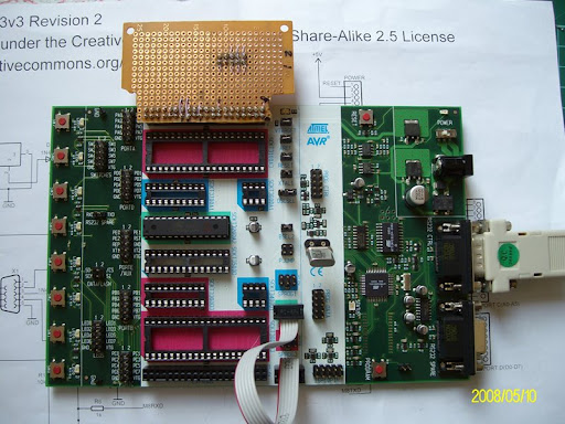
This is how the shield connected with Arduino.
I let the headers protrude out of the PCB on component side on purpose.
This way I can use the jump wires to connect them to the breadboard for other experiments.
Also I can clip the probe on them to monitor the Arduino ouputs or inputs.
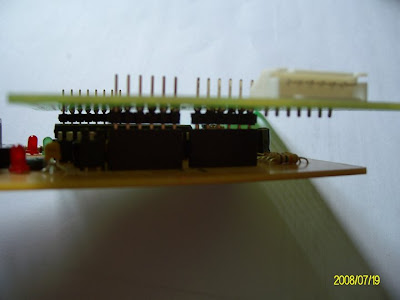
The Nunchuck shield mounted on Arduino.
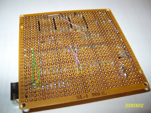
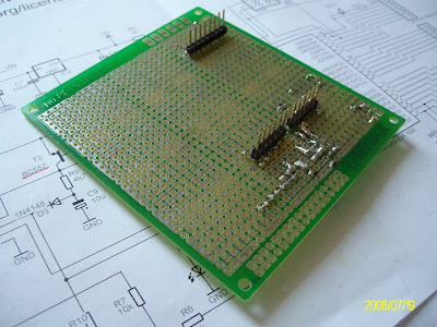
The soldering side of the Nunchuck shield.
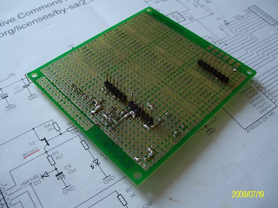
Another view of the soldering side of the Nunchuck shield.
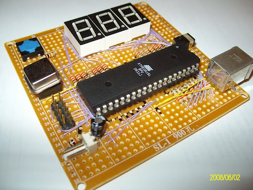
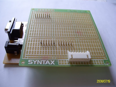
The component side of the Nunchuck shield. Most of the area is not used yet.
The left most area is planned to be the 3.3V and Nunchuck area.
Since the RESET button on Arduino is not easy to access on this configuration, a RESET button installed on the Nunchuck shield.
The Nunchuck shield mounted on Arduino.
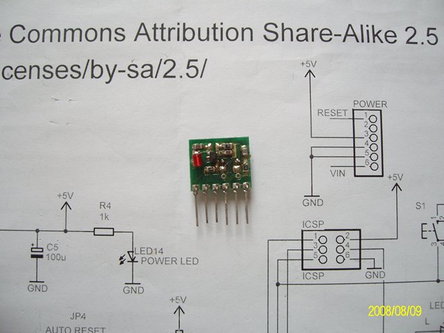
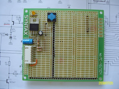
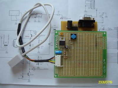
This is the first version of the Nunchuck shield I built.
The 3.3V regulator I used is LD1117. Simple and efficient to get 3.3V from 5~12V input voltage for Nunchuck.
I used two resistors as the level shifting devices between Nunchuck and Arduino.
But later on, I found it don't work. The low level can't reach 0.6V or lower.
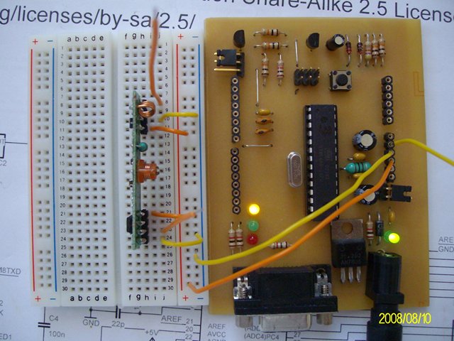
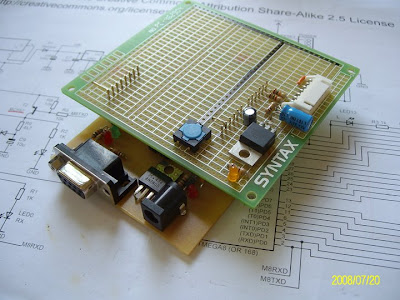
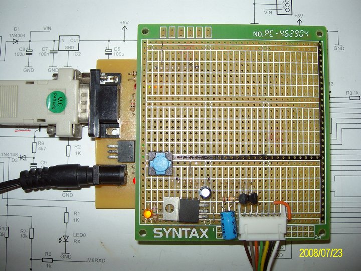
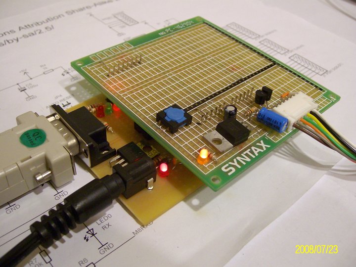
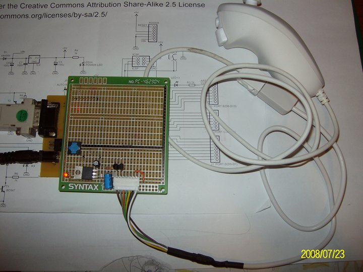
Power on the Arduino and Nunchuck shield.
The amber LED on the Nunchuck shield is power indicator of 3.3V.
The Nunchuck extension cable connected.
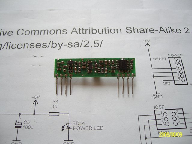
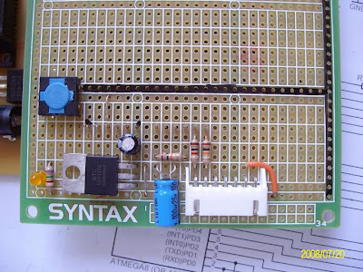
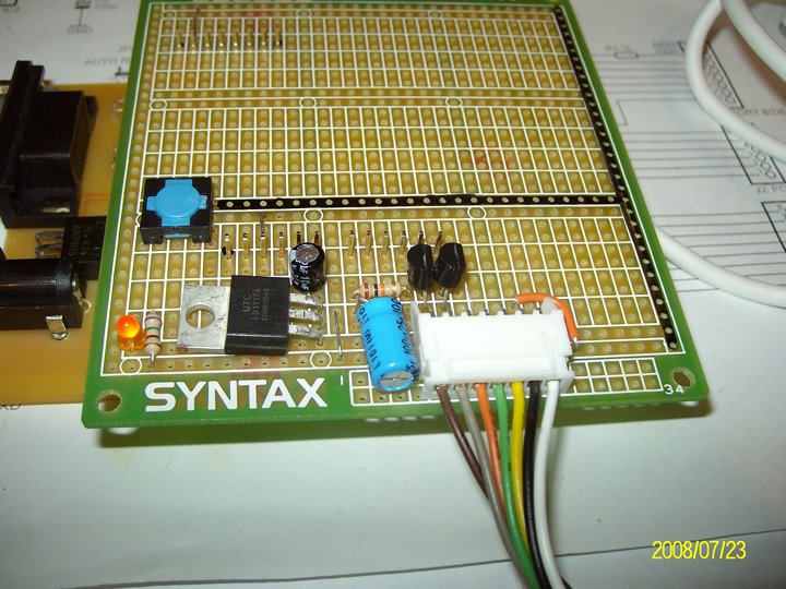
This is the 3rd (final) version of the Nunchuck shield board.
Actually I'd tried to replace the resistors with diode (1N4007) to try to get the logic low level to 0.6V. But it didn't work either. So in the final version, I used two N-channel MOSFET (2N7000) as the level shifters. The logic low level now reaches as low as 0.2~0.3V. It works perfectly now.
In fact, I found the N-channel MOSFET being the good device to drive high current (or power) circuits for MCU designs.
See the two TO-92 devices? They are the level shifters MOSFETs (2N7000).
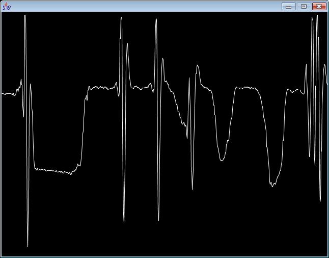
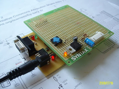
Arduino + Nunchuck shield board transimitting the Nunchuck readout via the serial port.
Arduino + Nunchuck shield board + Nunchuck on line.
The X-accelerometer readout when I waved the Nunchuck.